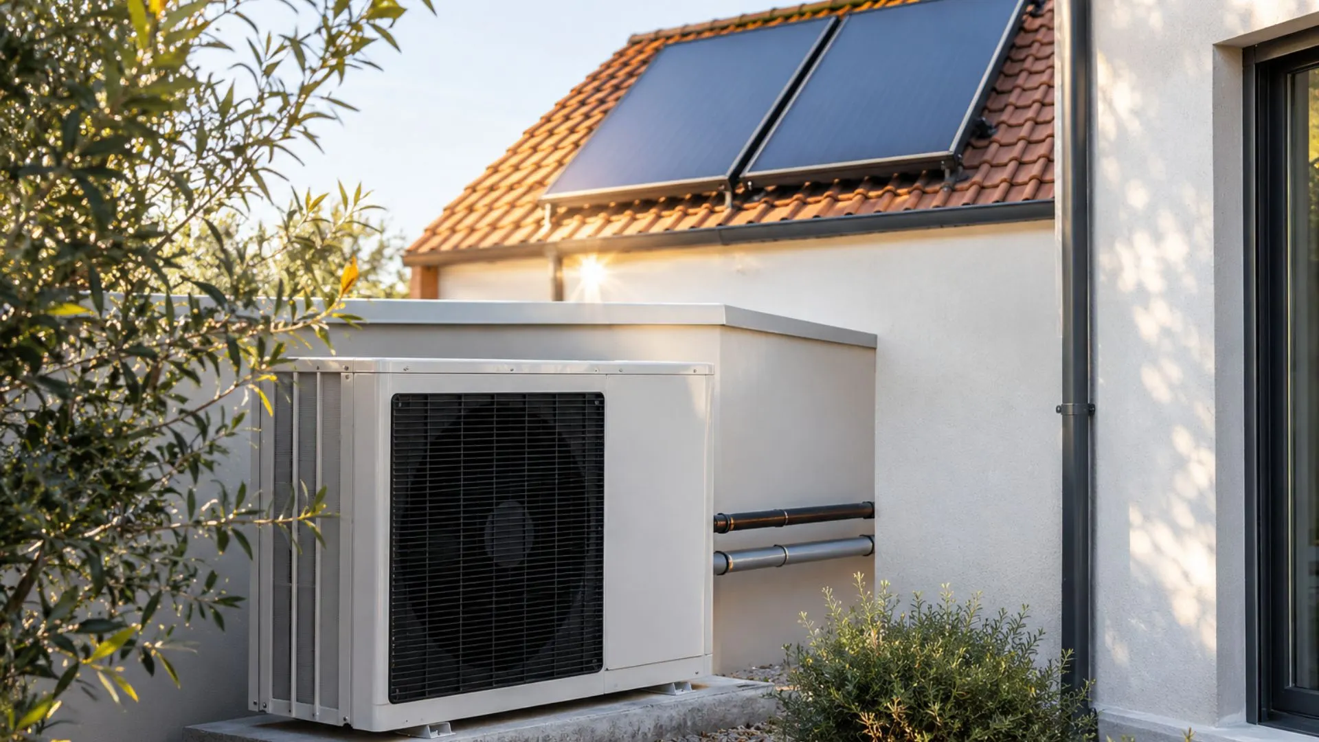
Air-source heat pumps and solar thermal systems have not changed the properties of piping materials. What has changed are the conditions under which those materials operate.
A system with a boiler and an aerothermal system can deliver similar flow rates and temperatures, and, even so, subject the piping system to different stresses: temperature variations linked to control, mechanical vibration from the compressor, the possible use of glycol-based mixtures, and complex routing in compact mechanical rooms.
This article analyzes these operating conditions, explains the relevant physical and chemical mechanisms, and translates them into design criteria. The choice of material is a consequence of that analysis, not its starting point.
Short answer
There is no material that is universally suitable or unsuitable for aerothermal and solar thermal systems. There are systems that are poorly compensated for thermal expansion, poorly decoupled from vibration, use fluid that does not meet specifications, or have more connection points than necessary. Copper and corrugated stainless steel perform correctly when the design, installation, and maintenance are done properly. The difference between them lies in the margin for error and the controls required by each solution.
What Sets the Operating Conditions of Air-Source Heat Pumps and Solar Thermal Systems Apart
It is important to distinguish verifiable facts from common generalizations.
Temperature Modulation and Variation
Fact: An inverter generator adjusts its power output by regulating the frequency of the power supplied to the compressor. Each machine has its own modulation range, as specified by the manufacturer; there is no universal range that applies to all compressors.
A detail that is often overlooked. Modulation does not eliminate starts and stops. Below the minimum modulation power, the equipment returns to operating in cycles. A system that is oversized relative to the actual load may accumulate more cycles than a properly sized one, regardless of the piping material.
Impact on the system. The supply temperature varies depending on the load, control, and operating conditions. These variations must be taken into account in long runs, at fixed points, and at changes in direction.
Daily Cycle and Stagnation in Solar Thermal Energy
Fact: The primary circuit absorbs heat during the day and cools down when solar radiation ceases. Under stagnation conditions—when there is no demand on the collector but sufficient irradiance—the fluid temperature far exceeds the normal operating temperature.
Guideline. The design temperature must be obtained from the collector documentation and test results in accordance with the current edition of ISO 9806 applicable to the project. A generic value does not substitute for the data specific to the collector.
Use of Antifreeze
Fact. In many closed solar thermal circuits, mixtures of water and glycol are used for freeze protection, in accordance with the design and the manufacturer’s instructions. In air-source heat pump systems, glycol may be used when there is a risk of freezing in the outdoor section or in the heat exchanger.
Note: This is not a universal requirement for air-source heat pump systems. It must be verified on a case-by-case basis for each installation.
Compact technical rooms
Fact: The hydraulic unit, DHW storage tank, buffer tank, expansion tank, and control system can all be concentrated within a very compact installation space.
Consequence. Actual access conditions determine the layout, the number of fittings, and the quality with which each joint can be installed and inspected.
Analysis
These conditions are not unique to geothermal heating systems: there are industrial systems that are far more demanding. The key point is that they occur in combination in residential and commercial installations, often without specific calculations for thermal expansion, support, or fluid maintenance.
This is an assumption, not a fact. It is plausible that some of the incidents attributed to the equipment stem from this combination of increasing demands and practices inherited from conventional installations. There are no publicly available Spanish statistics to quantify this, so it is presented as a hypothesis.
Thermal Cycling and Expansion: Calculations Come Before Materials
What Engineering Says
The linear expansion of a straight section is given by:
ΔL = α · L · ΔT
where α is the coefficient of linear expansion, L is the length of the section, and ΔT is the temperature difference.
As a general guide for material properties:
- Copper: on the order of 16.5 × 10⁻⁶ K⁻¹.
- Austenitic stainless steel 1.4404 (AISI 316L): on the order of 16 × 10⁻⁶ K⁻¹.
A conclusion worth clarifying: austenitic stainless steel does not expand any less than copper. With these values, a 10-meter straight section subjected to a temperature difference of 50 K experiences a change in length of about 8 millimeters in both cases. In design, the specified value for the material and the corresponding temperature range must be used.
What does differ, however, is the stiffness of the material. The modulus of elasticity of austenitic stainless steel is on the order of 200 GPa, compared to values on the order of 120 GPa for copper. Given equal stress and geometry, a stainless steel pipe would transmit a greater force to its fixed points. The actual response of a pipe, however, does not depend solely on the metal: geometry, wall thickness, layout, supports, fixed points, and joints all play a role.
Where the problem occurs
Dilation causes tension when movement is restricted. Common situations include:
- Sections anchored at both ends without a properly sized compensation solution.
- Guide clamps tightened so tightly that they act as fixed points.
- Openings in slabs or partitions without sleeves or clearance.
- Changes in direction near a fixed point that are subjected to movement for which they were not designed.
RITE (Royal Decree 1027/2007, as amended) requires in section IT 1.3.4.2.6 that temperature-induced length changes be compensated for to prevent breakage. This is a regulatory requirement, not a manufacturer’s recommendation. Compliance can be achieved through changes in direction, hangers, expansion joints, or other technically appropriate solutions based on the calculation; the regulation does not impose a single support methodology.
What Are the Benefits of Corrugated Geometry?
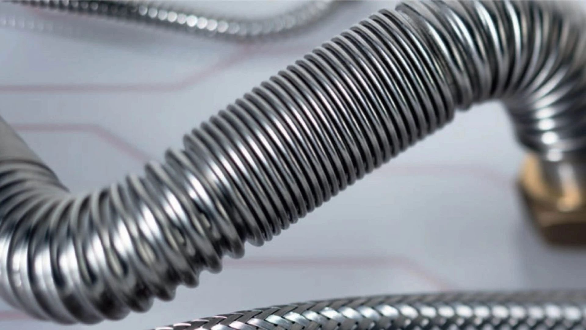
The corrugated design provides flexibility in routing. It allows for changes in direction without the need for fittings and facilitates routes with geometric flexibility, which is particularly advantageous in locations where it is difficult to install clamps or expanders: low-clearance suspended ceilings, crawl spaces, and equipment rooms with a high density of equipment.
It is important to state this clearly: this property stems from the geometry, not from the stainless steel itself. A smooth, rigid stainless steel tube would present the same compensation problem as a rigid copper tube—and would actually be even stiffer.
Geometric flexibility does not equate to a quantified axial compensation capacity. The pipe still requires support based on its diameter and operating conditions, and must comply with the minimum bend radius specified by the manufacturer, which in the CATS system ranges from 1.20 to 1.70 times the outer diameter.
Compressor vibration: what is transmitted and how it is controlled
What Engineering Says
A compressor generates mechanical excitation at its operating frequency and its harmonics. In an inverter-driven system, that frequency varies within the range specific to each machine, which broadens the frequency band that the piping-support assembly may experience.
The relevant failure mechanism is not overload failure but fatigue: the accumulation of stress cycles of moderate amplitude in areas where stress is concentrated. In a hydraulic system, these areas are predictable:
- Section and stiffness transitions—that is, where the pipe enters a fitting.
- Heat-affected zones from welding, where the microstructure has changed.
- Fixed points and rigid fasteners near the equipment.
- Cantilevered sections or sections with excessive spacing between supports.
How It Is Monitored
Control begins outside the pipe: the unit’s base and anti-vibration mounts, a proper connection at the equipment-to-network interface, and an initial mounting point sufficiently far from the equipment, in accordance with the manufacturer’s instructions and the project specifications.
When excitation enters the system, the response depends on the system as a whole—material, geometry, type of joint, quality of workmanship, and support—and not on a single variable.
It is incorrect to attribute vibration fatigue to copper as a material. Copper has well-characterized fatigue behavior and is widely used in refrigeration circuits subjected to vibration. What is sensitive to vibration are poorly executed joints and poorly supported sections, regardless of the material.
What Are the Benefits of a Corrugated Design?
The flexibility of the pipe can facilitate geometric decoupling between the equipment and the network. In addition, addressing certain changes in direction through bending reduces the number of fittings and stiffness discontinuities.
It is a benefit that complements proper design, not an alternative to it. Without specific system testing, no quantified vibration-damping capacity or fatigue resistance should be attributed to the pipe.
Fluid Chemistry: Maintenance and Compatibility Window
What Engineering Says
A new, properly formulated, and inhibited glycol-based coolant can be compatible with both copper and stainless steel. It is important to note this before considering anything else. Compatibility must be verified using the formulator’s data sheet for all metals, gaskets, and circuit components.
Degradation accelerates with temperature, oxygen, and time. The mechanism is described in the literature on heat-transfer fluids:
- Glycols exhibit good stability under the conditions specified by their formulator, but they can undergo oxidative degradation when exposed to high temperatures and air.
- This degradation can generate acidic byproducts, deplete the fluid’s alkaline reserve, and reduce the effectiveness of the inhibitors.
- Top-offs with untested water introduce oxygen, chlorides, hardness, and other salts that alter the circuit’s chemistry.
In solar thermal systems, this process is accelerated because periods of stagnation subject the fluid to the highest temperatures of its entire life cycle. Therefore, the condition of the fluid cannot be determined solely by its concentration.
How Each Material Responds
No material is universally immune. The fact that the UNE-EN 12502 series devotes one section to copper and another to stainless steels is the best proof that each has its own risk factors.
- Copper. Its behavior depends on the stability of its protective layers, which in turn depends on the composition of the water or fluid, the pH, dissolved oxygen, and temperature. UNE-EN 12502-2 lists the factors that influence the likelihood of corrosion of copper and its alloys in water distribution and storage systems.
- Austenitic stainless steel. Its protection comes from a chromium-rich passive layer. The composition of 1.4404 according to EN 10088 includes carbon limited to a maximum of 0.030%, chromium between 16.5% and 18.5%, nickel between 10% and 13%, and molybdenum around 2% to 2.5%. The low carbon content—the “L” in the designation—reduces the precipitation of chromium carbides in heat-affected zones. Molybdenum improves resistance to pitting corrosion, an effect quantified by the PREN index = %Cr + 3.3 · %Mo + 16 · %N.
Their specific risk factor is chlorides. Austenitic stainless steels are susceptible to pitting and, under certain conditions, chloride-induced stress corrosion cracking, especially at elevated temperatures. UNE-EN 12502-4 lists the applicable influencing factors. Ignoring this would be just as careless as claiming that glycol destroys copper.
Necessary clarification. It cannot be universally stated that 316L tolerates any drop in pH better than copper. The answer depends on the fluid formulation, pH, chlorides, temperature, oxygen, inhibitors, and the combination of metals present in the system.
Operational Conclusion
The material defines a compatibility window. Maintenance determines whether the fluid remains within that window.
A protocol must follow the fluid data sheet and the system maintenance plan, and include, where applicable:
- Monitor the pH and alkaline reserve using the method specified by the formulator.
- Verification of glycol concentration and freeze protection.
- Top off with treated and analyzed water; never use untreated tap water.
- Bleed the system and check for air ingress, which triggers the oxidative pathway.
- Replace the fluid according to the formulator’s instructions and the circuit’s thermal history, paying special attention to solar circuits prone to frequent stagnation.
Joints: A Design Variable, Not a Construction Detail
What Engineering Says
Joints are critical points in any network. Their number, accessibility, and quality of workmanship must be considered as early as the design phase.
Reducing the number of joint operations also reduces the number of points that must be installed, tested, and inspected; however, this alone does not allow for quantifying the probability of failure.
What Happens at Certain Facilities
In a rigid piping system, each change in direction may require fittings and new connection operations. In a flexible piping system, certain changes in direction can be achieved by bending the pipe.
Each additional joint involves:
- Assembly time and materials.
- A discontinuity in geometry or stiffness, which is significant in the presence of vibration.
- An operation whose quality depends on access, work position, and procedure.
- A point that must be inspectable throughout its service life.
In capillary soldering, thermal proximity to other components must also be managed, which, in a compact enclosure, dictates the assembly sequence.
What Are the Benefits of a Curved Layout?
Reducing the number of joints does not improve the quality of the remaining ones: it simply reduces their number and the associated operations. This offers advantages in terms of installation, inspection, and labor costs, but it is not a guarantee of leak-tightness.
Corrugated pipe replaces fittings with bends, but requires adherence to the minimum radius, avoidance of kinks, and proper cutting and fitting. A bend with a radius smaller than the allowable minimum reduces the flow cross-section; a poorly fitted joint loses its watertightness just like a poorly executed weld.
Temperature: Identify the pipe, joints, and insulation
The service limit applies to the entire system, not just the metal. This point warrants clarification because there are figures circulating that are difficult to verify.
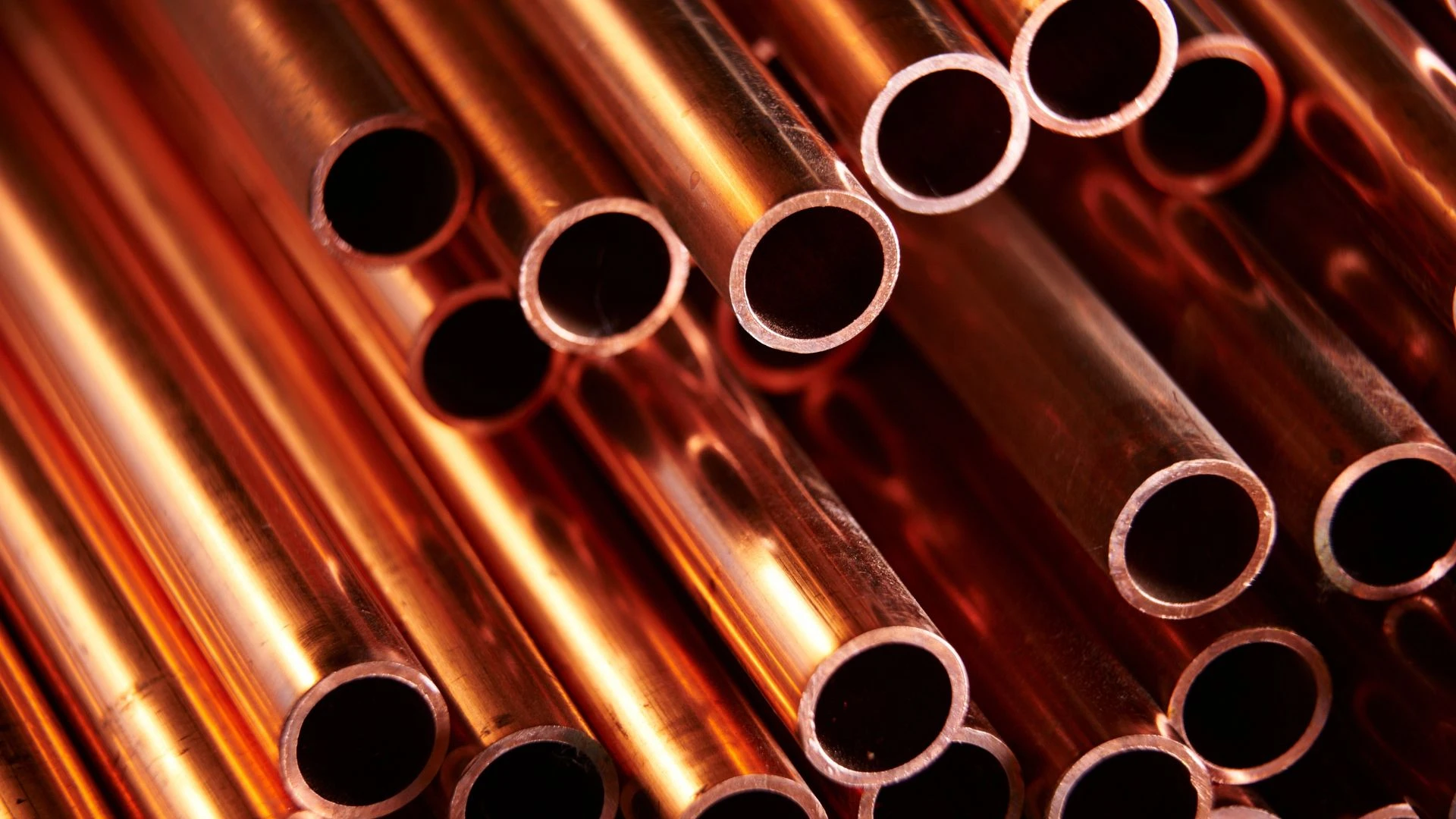
Copper. UNE-EN 1057 specifies seamless round copper tubes for water and gas in plumbing and heating applications. The permissible temperature for a specific installation depends on the pipe, the metallurgical condition, the pressure, the type of joint, the fittings, and the manufacturer’s documentation. This article does not assign generic, non-traceable limits to copper.
Austenitic stainless steel. The metal retains useful properties well beyond the range of a building’s heating system. The practical limit of the system as a whole is usually determined by the non-metallic components: gaskets, insulation, and fittings.
CATS solar system line. AZ specifies a continuous operating temperature of up to 200 °C for the version with PES fiber coating and recommends Klingersil C4400 gaskets for that application. This is manufacturer data referring to the combination of the pipe and insulation in that specific configuration, and it must be cited as such.
Design Criteria. In solar thermal systems, the design temperature of the primary circuit is not the operating temperature but rather the stagnation temperature of the collector, determined in accordance with the current edition of ISO 9806 applicable to the project. Piping, insulation, joints, air vents, the expansion tank, and its pre-tank must be compatible with the calculated conditions.
Hydraulics: The Cost of Corrugation and the Savings It Provides
An article that omitted this section would not stand up to scrutiny by a hydraulic engineer.
Fact: A corrugated wall has a higher effective roughness than a smooth pipe of the same internal diameter. Under turbulent flow conditions, a higher friction factor results in a greater distributed pressure drop per linear meter.
Countermeasure. A curved run can eliminate elbows and reduce localized losses. The hydraulic balance must be calculated over the entire run: it cannot be assumed that the reduction in fittings will compensate for the distributed loss in the pipe.
Design criteria. The pressure drop must be calculated using the data from the technical specifications of the pipe used, the design flow rate, the length, any special features, and the properties of the fluid at the operating temperature. Sizing the pipe by analogy with a smooth pipe of the same nominal diameter is a mistake. The result determines the selection of the circulator and, if applicable, its diameter. In air-source heat pump systems, the nominal flow rate and the maximum allowable pressure drop specified by the generator manufacturer also play a key role.
Clarification on bending. AZ notes that the corrugation profile allows bending within the minimum radius without unduly reducing the flow cross-section, thereby preventing the constrictions associated with improperly executed bends. This statement pertains to the pipe’s behavior during bending, not to pressure drop in a straight pipe. These are distinct issues and should not be confused.
Limitations of Stainless Steel Corrugated Tubing to Consider
Neutrality requires that they be stated explicitly.
- Cost. The price per meter and the cost of accessories must be compared on a project-by-project basis. The relevant assessment is the total installed cost: materials, accessories, labor, tools, and installation time. Copper is also subject to price volatility.
- Specific fittings and tools. The system requires its own fittings and a specific installation procedure. It is not interchangeable with generic tools.
- Distributed pressure drop. Higher than that of smooth tubing with the same internal diameter, as previously explained. It must be calculated using product-specific data.
- Learning curve. The installer must master perpendicular cutting, minimum radius, torque control, and fitting installation.
- Chlorides. Austenitic stainless steels are inherently sensitive to chlorides; this must be considered in water with high chloride levels and in marine environments, both inside and outside the pipe.
- Metal-to-metal transitions. These must be evaluated based on the fluid, aeration, surface area ratio, and circuit design, and resolved using compatible fittings.
- Minimum bend radius. The specified value for each diameter and configuration must be adhered to.
- System Limits. Gaskets, insulation, fittings, and accessories can control pressure and temperature even if the metal can withstand higher conditions.
Decision Framework Based on Installation Conditions
The table does not compare materials. It translates each service condition into the design criterion that governs it and into the variable that must be reviewed.
| Current condition | Dominant mechanism | Design criterion | Variable to be checked on site |
|---|---|---|---|
| Temperature variation due to regulation | Expansion and contraction | Calculation of movements and compensation in accordance with RITE | Sections between fixed points and movement zones |
| Long straight sections | Cumulative expansion | ΔL = α·L·ΔT and dimensioned compensation solution | Length, temperature drop, and applicable coefficient |
| Compressor near the network | Vibration fatigue | Decoupling of the equipment and proper support | Vibration dampers, primary mounting, and cantilevers |
| Glycol circuit | Fluid degradation and corrosion | Maintenance plan and compatibility of all materials | Concentration, pH, alkaline reserve, and aeration |
| Solar system leaks | Thermal peak on fluid and components | Sizing based on collector temperature according to ISO 9806 | Compatibility of tubing, gaskets, insulation, and tank |
| Make-up water containing chlorides or salts | Localized corrosion and deposits | Water Analysis and Treatment in Accordance with UNE-EN 12502-2 and -4 | Chlorides, hardness, conductivity, and pH |
| Many changes in direction | Increased number of connection operations | Optimization of the entire layout | Number, access, and inspection of joints |
| Compact utility room | Quality of execution dependent on access | Joint system that can be installed and inspected in that position | Actual workspace per joint |
| Retrofit with installation while the system is in service | Downtime and compatibility | Transition plan and sequence of work | Downtime window and compatible accessories |
| Simple layout and tight budget | Total installed cost | Comparison by project | Materials, fittings, labor, and tools |
Interpreting the table. The more conditions that apply simultaneously, the greater the importance of route flexibility, the reduction in connection operations, and maintainability. When the route is simple and the conditions are under control, the total cost, availability, and the experience of the installation team carry greater weight. The table serves as a guide for decision-making; it does not replace calculations or the manufacturers’ instructions.
Where does the CATS system fit into this analysis?
This section distinguishes the product’s stated performance characteristics from the general technical analysis.
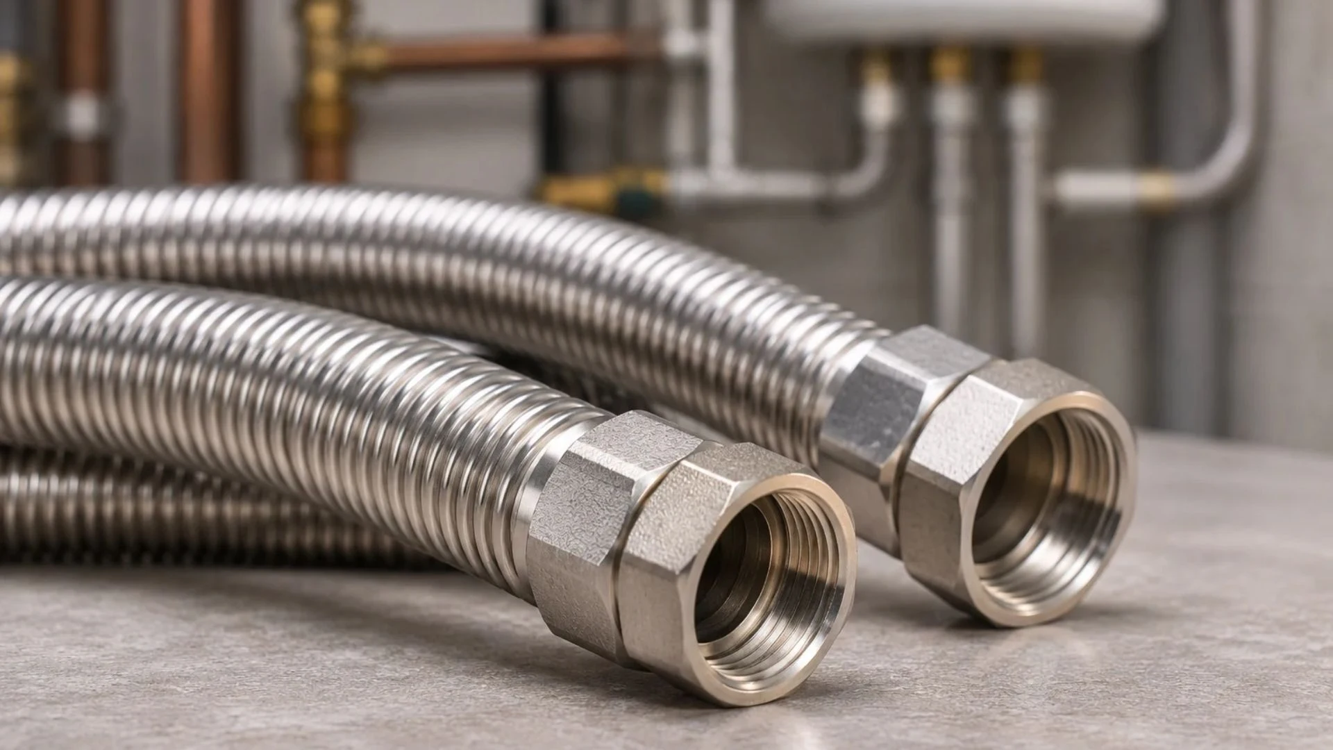
CATS is an assembly system consisting of austenitic stainless steel corrugated tubing and compatible fittings, distributed in Spain by AZ Broquetas and manufactured by AZ Intec. The product range and steel grade depend on the configuration and application and must be verified in the current data sheet.
What the system offers under the analyzed conditions, in verifiable terms:
- Complex layouts. This method allows for changes in direction by hand-bending the pipe—for diameters ranging from DN8 to DN25, without fittings—within a minimum radius of 1.20 to 1.70 times the outer diameter. In a run with multiple changes in direction, this means fewer jointing operations to perform, check, and inspect.
- Expansion and vibration. Provides geometric flexibility to the layout, which is useful where there is no space for expansion joints or expansion devices. It does not replace compensation calculations, support systems, or equipment vibration dampers.
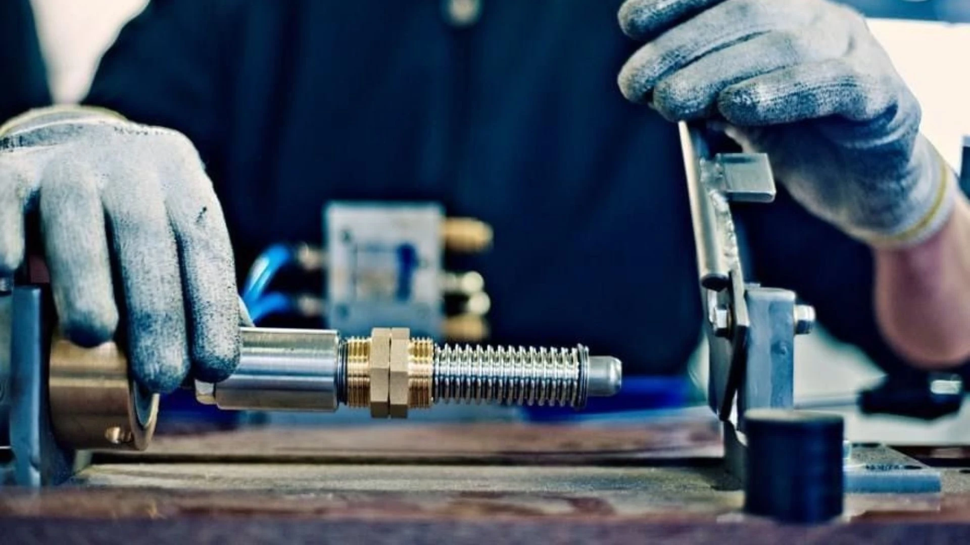
- Connection Installation. The connection can be made on-site using the CATS 120 press or the C-Klip system, which does not require special tools. AZ certifies a metal-to-metal seal without additional sealant for the transition fitting between corrugated solar tubing and copper; this certification does not apply to all system fittings.
- Fluid chemistry. Compatibility must be verified for the specific steel grade, gaskets, fittings, and formulation of the circuit.
- Solar thermal. AZ specifies a continuous operating temperature of up to 200 °C for the version with a PES fiber coating that provides protection against ultraviolet radiation, and specifies Klingersil C4400 gaskets for that product line.
- Retrofit. It offers copper transition fittings, allowing for modifications to existing systems without necessarily having to replace the entire piping run.
Complete technical data, diameters, pressures, radii, and certifications by configuration: az-broquetas.es/caracteristicas-tubo-corrugado-inox
Material-to-material comparison between corrugated stainless steel and copper: az-broquetas.es/tubo-corrugado-inox-vs-cobre
Certain system configurations are DVGW-certified for gas and drinking water applications in specific materials. The scope applies to each certified configuration and does not extend to the entire product line.
AZ Broquetas is part of the AZ Intec Group, which was founded in 1979 and consists of approximately 250 professionals in seven European cities, according to corporate information published by the company.
Conclusion
Four conditions define the operating environment of piping in air-source heat pump and solar thermal systems: temperature fluctuations related to control, mechanical vibration from the compressor, the possible presence of glycol, and the complexity of the piping layout and its connections.
None of these options disqualify copper, which remains the gold standard—with decades of installations in service and a training network that no other system can match. None of them makes corrugated stainless steel a universal solution: it requires specific hydraulic calculations, compatible fittings, training, chloride control, and adherence to system limits.
What changes is the operating margin. In a simple installation, with the equipment properly decoupled, the fluid controlled, and few accessible joints, various solutions are technically valid, and the decision may depend on cost or the installer’s preference. When certain conditions are present—limited space, multiple changes in direction, glycol, stagnation, difficult access—the flexibility of the layout and the reduction in connection operations shift from being a convenience during installation to a factor affecting reliability.
The right decision is made after analyzing the specific installation: the fluid and actual maintenance requirements, fill and make-up water, flow rate and allowable pressure drop, number of direction changes, installation space, vibration conditions, and design temperature.
Frequently Asked Questions
No. The linear expansion coefficients are of the same order of magnitude: approximately 16.5 × 10⁻⁶ K⁻¹ for copper and 16 × 10⁻⁶ K⁻¹ for austenitic stainless steel 1.4404. With these values, a 10-meter straight section with a temperature difference of 50 K will expand by approximately 8 millimeters in both cases. In design, the specified value for the material and the corresponding temperature range must be used. The practical difference lies not only in the metal but also in the pipe geometry, the layout, and the planned compensation solution. Geometric flexibility should not be assumed to be a quantified axial capacity without a calculation or specific data from the manufacturer.
Calculate the change in length using ΔL = α·L·ΔT and design the pipeline system to accommodate this change through changes in direction, bends, expansion joints, or other appropriate solutions, in accordance with section IT 1.3.4.2.6 of the RITE. Fixed and guided points must be correctly defined, and clearance and expansion sleeves must be provided at construction joints. A common mistake is to tighten guide clamps as if they were fixed points, which turns the entire section into a constrained element. A pipe’s flexibility should not be assumed to be sufficient without a calculation or specific data from the manufacturer.
As specified by the coolant manufacturer and the facility’s maintenance plan. This typically includes monitoring the glycol concentration and antifreeze protection, checking the pH and alkaline reserve using the method specified by the fluid formulator, topping off with treated and tested water, checking for air ingress and purging, and replacing the fluid based on its condition and thermal history. In solar thermal systems, the frequency must be adjusted based on the number of stagnation episodes, which are the events that subject the fluid to its highest temperatures. This is required for any type of piping material.
Not in absolute terms. The chromium-rich passive layer provides high resistance in many environments, and the molybdenum in 316L improves resistance to pitting corrosion, an effect quantified by the PREN index. However, austenitic stainless steels can be susceptible to pitting corrosion and, under certain conditions, stress corrosion cracking in the presence of chlorides, especially at elevated temperatures. The UNE-EN 12502-4 standard lists the applicable risk factors. The fluid, the fill and makeup water, and the environment surrounding the pipe must all be evaluated.
This is not a problem attributable to the material. Fatigue is related to the amplitude and number of cycles, as well as to stress concentrations: stiffness transitions, areas affected by welding, rigid fixings near the equipment, and cantilevered sections. It is first controlled in the equipment itself, using a test bench and anti-vibration mounts, and at the interface with the power grid. A flexible layout facilitates geometric decoupling and reduces stiffness discontinuities, but it does not replace anti-vibration mounts nor does it, on its own, guarantee a specific fatigue resistance.
Per linear meter, yes: a corrugated pipe has a higher effective roughness than a smooth pipe of the same internal diameter, which increases the friction factor under turbulent flow conditions. On the other hand, the curved layout eliminates elbows and, with them, their localized pressure losses. The overall balance depends on the pipe run and can only be determined by calculating it using the data from the pipe’s technical specifications, the design flow rate, and the fluid properties. In aerothermal systems, this must also be compared with the nominal flow rate and the maximum pressure drop specified by the generator manufacturer.
At least eight pieces of data: the circuit fluid and the maintenance plan that will actually be implemented; the quality of the fill and makeup water, with particular attention to chlorides; the design flow rate and the generator’s allowable pressure drop; the sizing temperature, which in solar thermal systems is the stagnation temperature and not the operating temperature; number of direction changes and pipe connections in the layout; actual installation and inspection space; vibration conditions and equipment isolation; and compatibility of gaskets, fittings, and accessories. With this data, the decision is usually clear. Without it, any choice is a matter of preference, not a design criterion.